
|
Product Details:
Payment & Shipping Terms:
|
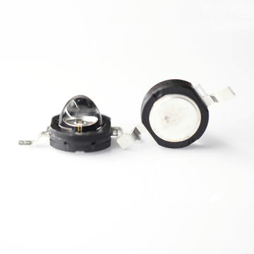
| Product Name: | 1W & 3W High Power Purple LED | Package: | COB LED |
|---|---|---|---|
| Emitted Color: | White | Product Number: | DL-HP10UV |
| Color Temperature: | 405nm | Forward Voltage: | 3.5V@350mA,4.2V@700mA |
| Forward Current: | 350mA,700mA | Luminous Flux: | 5-15LM/1W,15-30LM/3W |
| Viewing Angle: | 130 Deg | ||
| Highlight: | 365nm uv led,uv led chip |
||
This is our 1W & 3W High Power Purple LED,there are two Watts when the current is different.
| Part No. | Chip Material | Lens Color | Source Color |
| DL-HP10UV | InGaN | Water Clear | Purple |
Features:
Descriptions:
Applications:
Absolute Maximum Ratings at Ta=25℃
| Parameters | Symbol | Rating | Units |
| Power Dissipation | PD | 1400 | mW |
| 2800 | |||
|
Peak Pulse Forward Current (1/10 Duty Cycle, 0.1ms Pulse Width) |
IFP | 500 | mA |
| 1000 | |||
| DC Forward Current | IF | 350 | mA |
| 700 | |||
| Reverse Voltage | VR | 5 | V |
| Operating Temperature Range | Topr | -20 to +80 | ℃ |
| Storage Temperature Range | Tstg | -30 to +100 | ℃ |
| Soldering Temperature | Tsol | 260℃ for 5 Seconds (Max.) | |
Notes:
1. It is strongly recommended that the temperature of lead be not higher than 55℃.
2. Proper current derating must be observed to maintain junction temperature below the maximum.
3. LEDs are not designed to be driven in reserve bias.
Electrical Optical Characteristics at Ta=25℃
| Parameters | Symbol | Min. | Typ. | Max. | Unit | Test Condition |
| Luminous Intensity [1] | IV | 320 | 340 | 360 | mW/Sr | IF=350mA(HP60) |
| 525 | 560 | 590 | IF=700mA(HP70) | |||
| Viewing Angle [2] | 2θ1/2 | --- | 130 | --- | Deg | IF=350mA/700mA |
| Peak Emission Wavelength[3] | λp | --- | 395 | --- | nm | IF=350mA/700mA |
| Dominant Wavelength | λd | --- | 405 | --- | nm | IF=350mA/700mA |
| Spectral Bandwidth | △λ | --- | 15 | --- | nm | IF=350mA/700mA |
| Forward Voltage | VF | 2.80 | 3.50 | 4.00 | V | IF=350mA |
| 3.00 | 3.70 | 4.20 | IF=700mA | |||
| Reverse Current | IR | --- | --- | 50 | µA | VR=5V |
Notes:
1. Luminous Intensity Measurement allowance is ± 10%.
2. θ1/2 is the off-axis angle at which the luminous intensity is half the axial luminous intensity.
3. The dominant wavelength (λd) is derived from the CIE chromaticity diagram and represents the single wavelength which defines the color of the device.
Reliability Test Items and Conditions:
The reliability of products shall be satisfied with items listed below:
Confidence level: 90%.
LTPD: 10%.
1) Test Items and Results:
| No. | Test Item | Test Hours/Cycles | Test Conditions | Sample Size | Ac/Re |
| 1 | Resistance to Soldering Heat | 6 Min |
Tsld=260±5℃, Min. 5sec |
25pcs | 0/1 |
| 2 | Thermal Shock | 300 Cycles |
H: +100℃ 5min ∫ 10 sec L: -10℃ 5min |
25pcs | 0/1 |
| 3 | Temperature Cycle | 300 Cycles |
H: +100℃ 15min ∫ 5min L: -40℃ 15min |
25pcs | 0/1 |
| 4 | High Temperature Storage | 1000Hrs. | Temp: 100℃ | 25pcs | 0/1 |
| 5 | DC Operating Life | 1000Hrs. | IF=350mA | 25pcs | 0/1 |
| IF=700mA | |||||
| 6 | Low Temperature Storage | 1000Hrs. | Temp: -40℃ | 25pcs | 0/1 |
| 7 | High Temperature/ High Humidity | 1000Hrs. | 85℃/85%RH | 25pcs | 0/1 |
2) Criteria for Judging the Damage:
| Item | Symbol | Test Conditions | Criteria for Judgment | |
| Min | Max | |||
| Forward Voltage | VF | IF=350mA/IF=700mA | --- | F.V.*)×1.1 |
| Reverse Current | IR | VR=5V | --- | F.V.*)×2.0 |
| Luminous Intensity | IV | IF=350mA/IF=700mA | F.V.*)×0.7 | --- |
*) F.V.: First Value.
Precautions For Use:
1. Over-current-proof
Though the high power LED has conducted ESD protection mechanism, customer must not use the device in reverse and should apply resistors for extra protection. Otherwise slight voltage shift may cause enormous current change and burn out failure would happen.
2. Storage
① Do not open moisture proof bag before the products are ready to use.
② Before opening the package, the LEDs should be kept at 30℃ or less and 90%RH or less.
③ The LEDs should be used within a year.
④ After opening the package, the LEDs should be kept at 30℃ or less and 70%RH or less.
⑤ The LEDs should be used within 168 hours (7 days) after opening the package.
⑥If the moisture absorbent material (silicone gel) has faded away or the LEDs have exceeded the storage time, baking treatment should be performed using the following conditions.
⑦ Pre-curing treatment: 60±5℃ for 24 hours.
3. Thermal Management
① Because the LED is a high power dissipation device, special and sufficient consideration in thermal management design must be made to optimize the thermal performance.
② Heat sink design is implemented in the device for an additional thermal connection. Since the device is capable of SMT process, tin must be spread both heat sink and solder pads areas to dissipate the heat.
③ A high thermal conductivity substrate, such as Aluminum or Copper plate etc, must be applied for external thermal management. It is strongly recommended that the outer heat sink or PCB dimension per LED can not be less than 25 × 25 × 1 (L × W × H) mm. The materials for outer heat sink can be FR4 on Aluminum, MCPCB, or FPC on Aluminum.
④ Special thermal designs are also recommended to take in outer heat sink design, such as FR4 PCB on Aluminum with thermal vias or FPC on Aluminum with thermal conductive adhesive, etc.
⑤ Sufficient thermal management must be conducted, or the die junction temperature will be over the limit under large electronic driving and LED lifetime will decrease critically.
4. Soldering Condition
① Soldering should not be done more than two times.
② While soldering, do not put stress on the LEDs during heating.
③ After soldering, do not warp the circuit board.
5. Soldering Iron
① For prototype builds or small series production runs it is possible to place and solder the LED by hand.
② Dispensing thermal conductive glue or grease on the substrates and follow its curing spec. Press LED housing to closely connect LED and substrate.
③ It is recommended to hand solder the leads with a solder tip temperature of 280°C for less than 3 seconds within once in less than the soldering iron capacity 25W. Leave two seconds and more intervals, and do soldering of each terminal.
④ Be careful because the damage of the product is often started at the time of the hand solder.
6. Handling Indications
① During processing, mechanical stress on the surface should be minimized as much as possible.
② Sharp objects of all types should not be used to pierce the sealing compound.
7. Caution in ESD
Static Electricity and surge damages the LED. It is recommended to use a wrist band or anti-electrostatic glove when handling the LED. All devices equipment and machinery must be properly grounded.
Contact Person: Mr. Chen
Tel: 86-755-82853859
Fax: 86-755-83229774
| Factory Address:6th Floor,D Building,Weihuada Industrial Park,Huaning Road,Dalang,Longhua District,Shenzhen City China | |
| Sales office:Room 2711, Huishang Center, Jiahui New City, No. 3027 Shennan Middle Road, Futian District, Shenzhen City, Guangdong Province China 518033 | |
| +86-755-82853859 | |
| sales@doublelight.com.cn | |