
|
Product Details:
Payment & Shipping Terms:
|
| Product Name: | 5mm Ultra Amber Flat Top Led | Emitted Color: | Ultra Amber |
|---|---|---|---|
| Peak Emission Wavelength: | 605nm | Chip Material: | AlGaInP |
| Lens Type: | Water Clear | Forward Voltage @20ma: | 1.8-2.5v |
| Viewing Angle: | 100Deg | ||
| Highlight: | 700mcd LED Light Emitting Diode,605nm LED Light Emitting Diode,5mm Cylindrical Dip Led Diode |
||
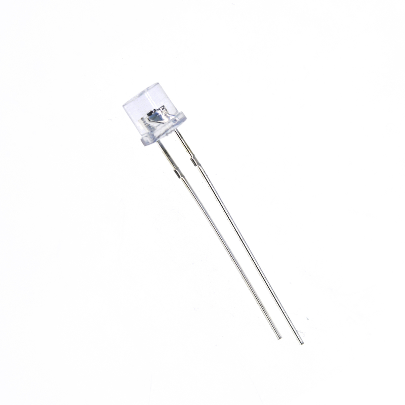
5mm Cylindrical with Flange Ultra Amber light emitting diode chip 5mm flat top dip led diode
Datasheet:DL-503UACE-3UA100.pdf
1. Popular T-1 3/4 diameter package.
Package Dimension:
![]()
| Part No. | Chip Material | Lens Color | Source Color |
| DL-503UACE-3UA100 | AlGaInP | Water Clear | Ultra Amber |
Notes:
1. All dimensions are in millimeters (inches).
2. Tolerance is ± 0.25 mm (.010″) unless otherwise noted.
3. Protruded resin under flange is 1.00 mm (.039″) max.
4. Specifications are subject to change without notice.
Absolute Maximum Ratings at Ta=25℃
| Parameters | Symbol | Max. | Unit |
| Power Dissipation | PD | 73 | mW |
|
Peak Forward Current (1/10 Duty Cycle, 0.1ms Pulse Width) |
IFP | 100 | mA |
| Forward Current | IF | 25 | mA |
| Reverse Voltage | VR | 5 | V |
| Operating Temperature Range | Topr | -40℃ to +85℃ | |
| Storage Temperature Range | Tstg | -40℃ to +100℃ | |
|
Lead Soldering Temperature [4mm (.157″) From Body] |
Tsld | 260℃ for 5 Seconds | |
Electrical Optical Characteristics at Ta=25℃
| Parameters | Symbol | Min. | Typ. | Max. | Unit | Test Condition |
| Luminous Intensity * | IV | 400 | 700 | --- | mcd | IF=20mA (Note 1) |
| Viewing Angle * | 2θ1/2 | --- | 100 | --- | Deg | IF=20mA (Note 2) |
| Peak Emission Wavelength | λp | --- | 605 | --- | nm | IF=20mA |
| Dominant Wavelength | λd | --- | 600 | --- | nm | IF=20mA (Note 3) |
| Spectral Line Half-Width | △λ | --- | 35 | --- | nm | IF=20mA |
| Forward Voltage | VF | 1.80 | 2.00 | 2.50 | V | IF=20mA |
| Reverse Current | IR | --- | --- | 10 | µA | VR=5V |
Notes:
1. Luminous Intensity Measurement allowance is ± 10%.
2. θ1/2 is the off-axis angle at which the luminous intensity is half the axial luminous intensity.
3. The dominant wavelength (λd) is derived from the CIE chromaticity diagram and represents the single wavelength which defines the color of the device.
Contact Person: Mr. Chen
Tel: 86-755-82853859
Fax: 86-755-83229774
| Factory Address:6th Floor,D Building,Weihuada Industrial Park,Huaning Road,Dalang,Longhua District,Shenzhen City China | |
| Sales office:Room 2711, Huishang Center, Jiahui New City, No. 3027 Shennan Middle Road, Futian District, Shenzhen City, Guangdong Province China 518033 | |
| +86-755-82853859 | |
| sales@doublelight.com.cn | |