
|
|
Product Details:
Payment & Shipping Terms:
|
| Product Name: | 0.40 Inch LED Digital Display | Source Color: | Hyper Red |
|---|---|---|---|
| Peak Emission Wavelength: | 632nm | Chip Material: | AlGaInP |
| Forward Voltage @20ma: | 3.3V | Luminous Intensity: | 50.0mcd |
| Highlight: | 632nm Triple Digit Numeric Displays,AlGaInP Triple Digit Numeric Displays,0.40" 7 Segment Led Display |
||
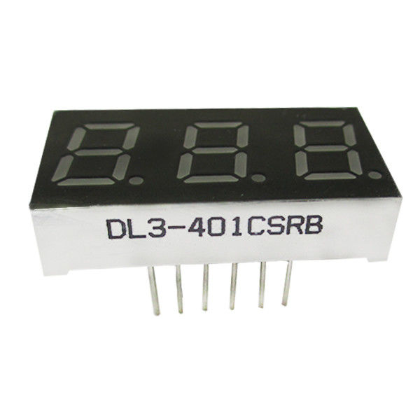
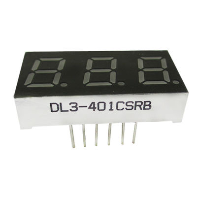
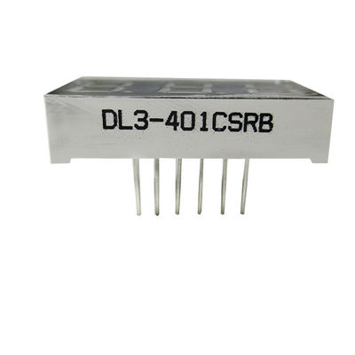
0.40" Triple Digit Numeric Displays 3 digit 7 segment display datasheet
Features:
1. 0.40″ (inch) digit height.
2. Excellent segment uniformity.
3. Sold state reliability.
4. Industrial standard size.
5. Low power consumption.
6. The product itself will remain within RoHS compliant Version.
Descriptions:
1. The DL3-401XSRA series is a lager10.20mm (0.40″) high seven segments display designed for viewing
distances up to 7 meters.
2. These displays provide excellent reliability in bright ambient light.
3. These devices are made with white segments and gray surface.
Applications:
1. Audio equipment.
2. Instrument panels.
3. Digital read out display.
Device Selection Guide:
| Model No. | Chip Material | Source Color | Description |
| DL3-401ASRA | AlGaInP | Hyper Red | Common Anode |
| DL3-401CSRA | Hyper Red | Common Cathode |
Package Dimension:
![]()
Notes:
1. All dimensions are in millimeters (inches).
2. Tolerance is ± 0.25 mm (.010″) unless otherwise noted.
3. Specifications are subject to change without notice.
Triple Digit Numeric Displays Absolute Maximum Ratings at Ta=25℃
| Parameters | Symbol | Max. | Unit |
| Power Dissipation Per Segment | PD | 100 | mW |
|
Peak Forward Current Per Segment (1/10 Duty Cycle, 0.1ms Pulse Width) |
IFP | 100 | mA |
| Forward Current Per Segment | IF | 25 | mA |
| Dating Linear From 50℃ | 0.4 | mA/℃ | |
| Reverse Voltage | VR | 5 | V |
| Operating Temperature Range | Topr | -40℃ to +80℃ | |
| Storage Temperature Range | Tstg | -40℃ to +85℃ | |
| Soldering Temperature | Tsld | 260℃ for 5 Seconds | |
Triple Digit Numeric Displays Electrical Optical Characteristics at Ta=25℃
| Parameters | Symbol | Min. | Typ. | Max. | Unit | Test Condition |
| Luminous Intensity | Iv | 30.0 | 50.0 | --- | mcd | IF=20mA (Note 1) |
| Luminous Intensity Matching Ratio (Segment To Segment) | Iv-m | --- | --- | 2:1 | IF=10mA | |
| Peak Emission Wavelength | λp | --- | 632 | --- | nm | IF=20mA |
| Dominant Wavelength | λd | --- | 624 | --- | nm | IF=20mA (Note 2) |
| Spectral Line Half-Width | △λ | --- | 25 | --- | nm | IF=20mA |
| Forward Voltage | VF | 3.0 | 3.3 | 4.0 | V | IF=20mA |
| Reverse Current | IR | --- | --- | 50 | µA | VR=5V |
Notes:
1. Luminous intensity is measured with a light sensor and filter combination that approximates the CIE eye-response curve.
2. The dominant wavelength (λd) is derived from the CIE chromaticity diagram and represents the single wavelength which defines the color of the device.
![]()
Contact Person: Mr. Chen
Tel: 86-755-82853859
Fax: 86-755-83229774
| Factory Address:6th Floor,D Building,Weihuada Industrial Park,Huaning Road,Dalang,Longhua District,Shenzhen City China | |
| Sales office:Room 2711, Huishang Center, Jiahui New City, No. 3027 Shennan Middle Road, Futian District, Shenzhen City, Guangdong Province China 518033 | |
| +86-755-82853859 | |
| sales@doublelight.com.cn | |