
|
Product Details:
Payment & Shipping Terms:
|
| Package: | DIP 3MM | Emitted Color: | Yellow Green& Ultra Yellow |
|---|---|---|---|
| Peak Emission Wavelength: | 565nm & 588nm | Chip Material: | GaP&GaAlAs |
| Lens Color: | Diffused | Forward Voltage @20ma: | Typ:2.20V |
| Viewing Angle: | 60Deg | Luminous Intensity: | 45/60mcd |
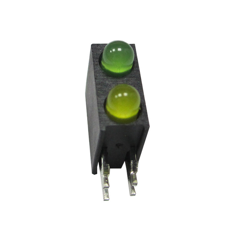
3.00mm Round Type Housing LED Lamps Yellow Green& Ultra Yellow bi color led
Features:
1.Low Power consumption.
2.High efficiency and low cost.
3.Chip material: GaP&GaAlAs
4.Emitted color : Yellow Green& Ultra Yellow
5.Good control and free combinations on the colors of LED lamps.
6.Good lock and easy to assembly.
7.Stackable and easy to assembly.
8.Stackable vertically and easy to assembly.
9.Versatile mounting on P.C board or panel.
10. Stackable horizontally and easy to assembly.
11. The product itself will remain within RoHS compliant version.
Descriptions:
1.ARRAY=Plastic Holder + Combinations of Lamps.
2.The array will easily mount be applicable on any panel up to.
Applications:
1.TV set
2.Monitor
3.Telephone
4.Computer
5.Circuit board
6.Used as indicators of indicating the Degree, Functions, Positions etc, in electronic instruments.
![]()
| Part No. | Chip Material | Lens Color | Source Color |
| DL-H30D-1YGUYD | GaP | Green Diffused | Yellow Green |
| AlGaInP | Yellow Diffused | Ultra Yellow |
Notes:
1. All dimensions are in millimeters (inches).
2. Tolerance is ±0.25mm (.010″) unless otherwise noted.
3. Protruded resin under flange is 1.00 mm (.039″) max.
4. Specifications are subject to change without notice.
Absolute Maximum Ratings at Ta=25℃
| Parameters | Symbol | Max. | Unit |
| Power Dissipation | PD | 75 | mW |
| Peak Forward Current (1/10 Duty Cycle, 0.1ms Pulse Width) |
IFP | 100 | mA |
| Forward Current | IF | 25 | mA |
| Reverse Voltage | VR | 5 | V |
| Operating Temperature Range | Topr | -40℃ to +80℃ | |
| Storage Temperature Range | Tstg | -40℃ to +85℃ | |
| Lead Soldering Temperature [4mm (.157″) From Body] |
Tsld | 260℃ for 5 Seconds | |
Electrical Optical Characteristics at Ta=25℃
| Parameters | Symbol | Emitting Color | Min. | Typ. | Max. | Unit | Test Condition |
| Luminous Intensity | IV | Green | 20 | 45 | --- | mcd |
IF=20mA (Note 1) |
| Yellow | 30 | 60 | --- | ||||
| Viewing Angle | 2θ1/2 | Green | --- | 60 | --- | Deg |
IF=20mA (Note 2) |
| Yellow | --- | 60 | --- | ||||
| Peak Emission Wavelength | λp | Green | --- | 565 | --- | nm | Measurement @Peak |
| Yellow | --- | 588 | --- | ||||
| Dominant Wavelength | λd | Green | --- | 568 | --- | nm |
IF=20mA (Note 3) |
| Yellow | --- | 590 | --- | ||||
| Spectral Line Half-Width | △λ | Green | --- | 20 | --- | nm | |
| Yellow | --- | 20 | --- | ||||
| Forward Voltage | VF | Green | 1.80 | 2.20 | 2.60 | V | IF=20mA |
| Yellow | 1.80 | 2.20 | 2.60 | ||||
| Reverse Current | IR | Green | --- | --- | 10 | µA | VR=5V |
| Yellow | --- | --- | 10 |
Notes:
1. Luminous intensity is measured with a light sensor and filter combination that approximates the CIE eye-response
curve.
2. θ 1/2 is the off-axis angle at which the luminous intensity is half the axial luminous intensity.
3. The dominant wavelength (λd) is derived from the CIE chromaticity diagram and represents the single wavelength
which defines the color of the device.
![]()
![]()
Contact Person: Mr. Chen
Tel: 86-755-82853859
Fax: 86-755-83229774
| Factory Address:6th Floor,D Building,Weihuada Industrial Park,Huaning Road,Dalang,Longhua District,Shenzhen City China | |
| Sales office:Room 2711, Huishang Center, Jiahui New City, No. 3027 Shennan Middle Road, Futian District, Shenzhen City, Guangdong Province China 518033 | |
| +86-755-82853859 | |
| sales@doublelight.com.cn | |